
PulseSensor_Amped_Arduino on github
PulseSensor_Amped_Processing_Visualizer on github
The image below is from the Arduino Serial Plotter. The red trace is live heart beat data, the yellow trace is the time between each beat (IBI), and the blue trace is beats per minute (BPM).

The PulseSensor works with littleBits, via littleBits's "Proto Bit". Cool Stuff. You can now put your heartbeat into your littleBits projects !
Proto Bit: http://littlebits.cc/bits/proto
]]>First up: How To Do Open Source
We got a nice pingback from OHS Park and their Staff Pics this week. They picked Ladvien's great post on the trials and tribulations in the making of a Homemade Pulse Sensor. Two weeks ago, he was the Fail of the Week over at Hackaday. Glad to hear that he worked out the kinks in his process! Here at Pulse Sensor, we support open and honest copies and improvements. That's what Open Hardware is all about!
What Open Hardware is NOT about is disingenuous ripoffs and selling what amounts to a bill-of-goods (def. 2). That's what happened to an unwary shopper from Eastern Europe when he purchased what he thought was a legit Pulse Sensor, but then he received the hardware with an incomplete kit (no ear clip, velcro parts, vinyl stickers, or even a cable). We don't even know if the hardware they are selling works or not. Here's a link to the counterfeit Pulse Sensor from Good Luck Buy.
DO NOT BUY PULSE SENSOR FROM GOOD LUCK BUY the name says it all.
We love Open Hardware here at Pulse Sensor, and we understand the potential risks and rewards of releasing all of our design plans. And we also realize that getting cloned means that we must be doing something right... But that doesn't mean that we will put up with sub-standard ripoffs which sully the good name of our product!
If you don't buy the Pulse Sensor from us directly (which is fine! we also love our resellers!) make sure the company is reputable and trustworthy! The companies that we have re-seller agreements with are Adafruit, Sparkfun, and Maker Shed. If you are finding our Pulse Sensor at a different supplier, please be aware and double check the source!
]]>
Pulse Sensor Getting Started Guide from yury g on Vimeo.
We are releasing an informative new video today. It illustrates the best practices for setting up the Pulse Sensor as a Finger Strap or Ear Clip, and thus getting best readings from a user. For your viewing please, the video is narrated by the voice of Christopher Walken.
]]>Tito Jankowski used the Pulse Sensor in a workshop and talk for TEDx Kids in Brussels. The opening of the above news segment shows lots of kids experimenting and playing with their hearts. Tito's full talk here.
Pulse Sensor Amped Arduino 1.1
Pulse Sensor Amped Processing 1.1
The new Arduino code contains an enhanced beat finding algorithm, and tidies up some inefficiencies since the last version.
We have also put together a detailed walk-through of the Arduino code for your edification.
]]>
We are announcing a big big upgrade to the Pulse Sensor today, with the release of Pulse Sensor Amped!
Pulse Sensor Amped adds
amplification and noise cancellation circuitry to our original Pulse Sensor hardware. It's
noticeably faster and easier to get reliable pulse readings. Also, Pulse
Sensor Amped works with either a 3Volt and 5Volt Arduino. We've
discontinued our previous Pulse Sensor models because this one is so darn good.
Lastly, we've also streamlined and improved the included Processing visualization software and Arduino code. This is our 3rd generation Pulse Sensor, and definitely our sweetest hardware and software creation to date.
PulseSensor meets Android:
]]> Also, the good folks at Make Magazine asked us to write a detailed article about the Pulse Sensor for the first 2012 issue. The "DIY SuperHuman" issue is all about bio-sensing. It's a great volume and worth getting if you are into that kinda thing. If you are reading this you can assume that you into that kinda thing....]]>


In an optical heart-rate pulse sensor, light is shot into a finger tip or ear lobe. The light either bounces back to a light sensor, or gets absorbed by blood cells. As you continue to shine light (into say a fingertip) and take light sensor readings, you quickly start to get a heart-beat pulse reading. The theory is easy to understand. In practice, it hard to master DIY optical heart-rate sensors, or get them operational at all. There are many tutorials online and in publications describing how to make DIY heart-rate sensors. Through our own personal interests we’ve tried to follow online guides but have generally failed or had unsatisfactory results. As professors, year after year, we see our students attempt to follow these published guides and also either fail in getting anything to work, or get poor results. It could very well be human/user-error on our parts. But from our view, making an optical pulse sensor is “easier said then done”. We set out to make our own optical heart-rate pulse senor that can be used in our own creative projects and also available to students, makers, game developers, mobile developers, artists, athletic trainers etc.... We had three goals for our sensor: 1) It had to actually work and be “plug and play” into Arduino (and related devices). 2) It should be super small and easy to place (sew, glue, clip) into wearables, sports, arts, or gaming applications. 3) It could be used as a teaching aid for instruction on working with sensors, data viz, and bio-feedback. After a few months of testing a gaggle of optical sensors and LED colors we found that it was not as easy as many suspect to get reliable heart-rate data through optical means. It was easy to get basic, gross, short-term data, but hard to get reliable readings assuming real-world scenarios and real-world user interaction. After much experimentation and development, we started to assemble a reliable heart-rate pulsesensor. We fabricated a few test boards and continued to iterate the design.

As we tired to "wear" the sensor, we discovered that we should make it look and feel like a 1/2 inch button. Its size allows it to clip to earlobs or fingertips easily. When we add "button holes" to the design it can be easily sewn or attached to various garments and fashion accessories. Thus the design turned into a button-sized PCB board that holds all the technology, hit all our goals, and is very cute and accessible to a novice or expert users/developers alike.
]]>


 ]]>
]]>
]]>
]]>
 ]]>
]]>
First, a description of how optical heart rate sensors work. Most kids have shined a flashlight through their fingers, or cheek, and seen the light glow through their flesh. It's a spooky-cool thing to do even as an adult. What it shows is that we are semi transparent. Most of the light is absorbed or reflected by our organs and tissues (skin, bone, muscle, blood), but some light will pass through our tissues if they are thin enough. When blood is pumped through your body, it gets squeezed into the capillary tissues, and the volume of those tissues increases very slightly. Then, between heart beats, the volume decreases. The change in volume effects the amount of light that will transmit through. This fluctuation is very small, but we can sense it with electronics. Here's how it's done.
 We start with a light source and a light detector. I'm using an Infrared LED, and a photodiode sensor. It's important that the two devices are matched well, so that the light wavelength output from the LED is detected strongly by the photodiode (see below for part numbers). The photodiode is essentially a teeny tiny solar cell, just like the panels on rooftops, but really small. It will generate a small voltage and current when it is blasted with photons. The Infrared LED is what we will use for our photon blaster.
The next thing we need is a way to amplify the tiny signal coming off of the photodiode. Happily enough, the configuration of this circuit is well-known in analog electronics circles as a 'Current to Voltage Converter' and it is a classic.
(Schematic drawn in Design Spark, an open source circuit layout software. Go Spark!)

I'm specifying a SA5230 Op Amp from ON Semi. I've also had success with Texas Instrument OPA177.
The photodiode is Osram SFH 203 P.
The LED is Everlight EL-IR204-A, peak wavelength at 940nm.
Here's a picture of the breadboarded circuit

I had to make one modification to the Photodiode, it needs to be shielded from ambient light, which generates alot of noise in the signal. Putting some heat shrink tubing around it worked great. If you plug this circuit into an O-scope, or some basic visualization software, you might get a waveform that looks like this:

Vertical height of the red line represents voltage. Horizontal axis is Time. The waveform here is usable, but as you can see, the pulse signal is distorted by even small movements. Also any misalignment or movement of the IR LED will muddy up the signal. It's hard enough to get this clear of a signal, even if you don't know anything about Low Pass filters and Op Amps. Once you get this far, having to overcome the challenge of building the circuit into an ergonomic and robust form pulls designers further away from getting to the fun part of building their cool project. Designers and hackers who want to use heartbeats end up spending too much time building sketchy work-arounds for the problems with this bulky hardware. Most of the time this will kill the project before it gets very far, and finished projects are clunky, hard to set up, not really repeatable, and look more like science demonstrations than anything else.
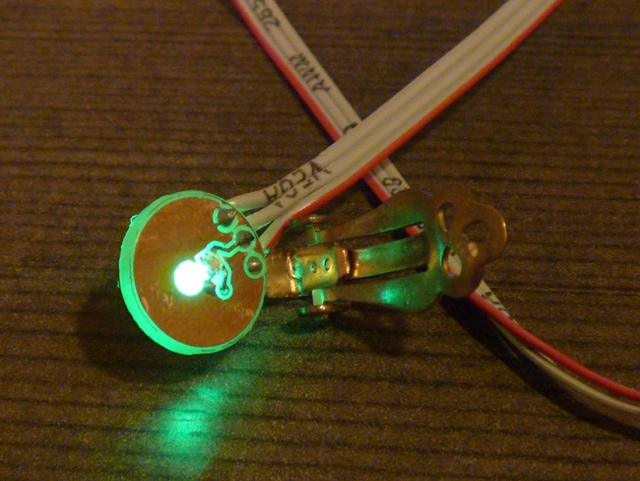
We wanted to make a Pulse Sensor that is small enough to be worn comfortably in many configurations, and immune to signal noise generated by moving around, or changes in ambient lighting conditions. In our search for the right components, we found a super small integrated circuit that has an on-board photodiode and op amp circuit combined. The super smallness means that we can maintain close, steady contact with the skin. This shields the sensor from changes in ambient light and makes noise from moving around minimal at most. Here is an example of our Pulse Sensor in action.
[youtube http://www.youtube.com/watch?v=mEXJyhBvgG8?hl=en&fs=1]
We made our Pulse Sensor small and easy to connect to Arduino so that you don't have to spend all your time tweaking hardware and can get down to the fun part of building your project. If you like our Pulse Sensor, please support it and become a backer at Kickstarter today!
Our plan is to open source the hardware design, and we will do a Full Monty on the Pulse Sensor here in the near future. Stay tuned!
-Joel
]]> We are starting our Kickstarter campaign today. Watch our video and help us fund the project! Thanks!]]>
 After a few months of testing a gaggle of techniques, we developed what we think is an innovative pulse sensor. Our prototype (and accompanying code) plugs right into Arduino and easily clips onto a fingertip or earlobe. It's super small too, button-sized with holes, so can be sewn into a garment as well. We'd like to manufacturer the actual pulse sensor, making it low-cost, and accessible for students, artists, and developers to use in their projects.
It also includes software for graphing BPM on screen. Included software also makes it easy to export live BPM data feed to software (or web app) of choice.
After a few months of testing a gaggle of techniques, we developed what we think is an innovative pulse sensor. Our prototype (and accompanying code) plugs right into Arduino and easily clips onto a fingertip or earlobe. It's super small too, button-sized with holes, so can be sewn into a garment as well. We'd like to manufacturer the actual pulse sensor, making it low-cost, and accessible for students, artists, and developers to use in their projects.
It also includes software for graphing BPM on screen. Included software also makes it easy to export live BPM data feed to software (or web app) of choice. ]]>
]]>