Open Hardware
Pulse Sensor is an open source hardware project by Joel Murphy and Yury Gitman.
We are happy to announce a new version of the Pulse Sensor Hardware! We call it Pulse Sensor Amped!
Here is a link to the Schematic (pdf)
Here is a link to the PCB design files (git)
Here is a link to the Datasheet(pdf)
Pulse Sensor is made with Design Spark, free circuit schematic and PCB layout editor. Download Design Spark here.
Stats: Diameter = 0.625" (~16mm)
Overall thickness = 0.125" (~3mm)
Cable length = 24" (~609mm)
Voltage = 3V to 5V
Current consumption = ~4mA at 5V
We made some changes to the original Pulse Sensor circuit, and we think you'll like them. The basic Pulse Sensor is still there, we are using the same ambient light sensor from Avago (APDS-9008), and the same green super bright reverse mount LED from Kingbright (AM2520ZGC09). The new version adds diode protection on the power line, so you can't break it if you plug it in backwards, and an active filter to make the pulse waveform brighter and easy for Arduino to find. The additional components make Pulse Sensor Amped increase in size a little to 5/8" diameter (was 1/2" diameter). The cable is still 24" long, and It's still got three holes around the outside edge for sewing it into just about anything.
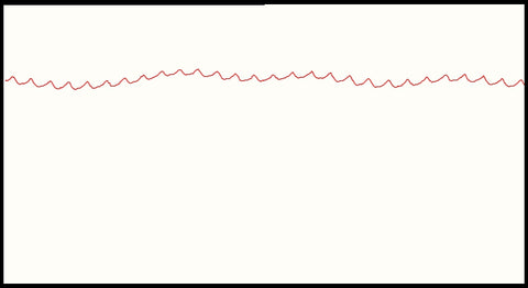
The effect of the active filter makes a huge difference in how the raw heartbeat waveform looks. The pervious version output the heartbeat waveform as a small saw-tooth wave riding on a DC voltage. Here's an image of what that looks like from the previous processing sketch.

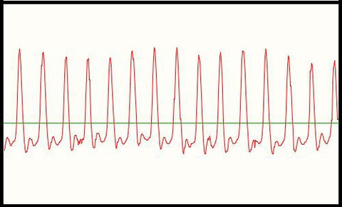
You can see that the pulse is there, but it's not the easiest signal to tease out with Arduino. The heartbeat waveform itself averages around 10 points high, but that nice little saw-tooth wave is riding on a fluctuating DC voltage. The new hardware version uses a filter and amplifier to increase the amplitude of the pulse wave and normalize the signal around a reference point. When the Pulse Sensor Amped is just sitting there, not in contact with any fingers or earlobes or other parts, the analog signal hovers around the mid-point of the voltage, or V/2. When Pulse Sensor Amped is in close contact with your fingertip or earlobe (or other part) the change in reflected light when blood pumps through your tissues makes the signal fluctuate around that reference point. In the image below the horizontal line is at V/2.

Arduino watches the analog signal from Pulse Sensor, and decides a pulse is found when the signal rises above the mid-point. That's the moment when your capillary tissues gets slammed with a surge of fresh blood. Then, when the signal drops below the mid-point, Arduino sees this and gets ready to find the next pulse. We have built in hysteresis to the rising and falling thresholds which you can adjust if necessary.
The story of how we came up with the Pulse Sensor follows below, and there are links to the previous hardware versions too.
p.s. Be sure to all see this blog entry for more development background: Anatomy of The DIY Heart Rate Monitor
The story of developing our Pulse Sensor hardware is long and convoluted. This page will hit the highlights of how we came up with the design.
The Current to Voltage Converter is a well known Op Amp circuit that invariably uses a photodiode as a current source, and is often used as a starting point for developing optical heart-rate monitors. After breadboarding a few using different Op Amps and Photodiodes, we designed a fairly universal Low Pass Filter for the output (passive RC. R: 100 C: 4.7uF). The next step was to shrink the hardware by designing with surface mount parts. In our search for SMT photodiodes, we came across a whole pile of ambient light sensors often used in phones and laptops to adjust LCD brightness. These things are sensitive to the visible spectrum, and because of the space requirements in handhelds, they are integrated photodiode / op amp / feedback network in a super teeny tiny itsy bitsy package (!!!). After testing a few models, we picked the Avago APDS-9008 (datasheet) because it has the best form factor for our needs. The peak sensitivity for this sensor is 565 nm, hence the green LED.
In deciding on which LED to use, we came across the reverse mount package from Kingbright (datasheet) purely by accident. We were looking for a super-bright green that matched my price point and had a really small profile. There were already problems with other surface mount LEDs because they are mostly taller than the sensor, which can cause the photodiode to saturate when your finger gets out of alignment. Getting the finger placement just right made it work, but it was too tedious for the user. Turns out Kingbright sells both standard mount and reverse-mount versions of their super-bright green, and we ordered a reverse-mount without knowing it. Now, usually I would curse this kind of mix up between the-part-you-thought-you-ordered and the-part-you-got (TPYTYO v TPYG). It is almost never a good thing. This time I stood up, paced around a bit, then did a little dance, and thanked my dog. The reverse mount LED solders to the back (duh) of the PCB and shines through a small hole (~2mm). This means that the only thing on the top of the board, the side you put your finger on, is the sensor. With this design, we can place the sensor very close to the skin, blocking out ambient light, and it becomes much more immune to noise resulting from movement.
The only thing left to say about the electronics, on this inaugural version, is that it is optimized for both 5V and 3V. The circuit can be tuned by changing R1 & R3. R1 determines how much current goes to the LED, and R3 is the load resistor on the APDS output. To optimize for 5V, use higher R1 and higher R3 (R1:1K, R3:22K). For best results at 3V tweak the other way. 470 is as low as I have gone with R1. The super-brightness of the LED will saturate the sensor at higher currents, and it does get warm even when it's running at 20mA. Better to stay cool. We want to know if you would like to see discrete 5V and 3V versions. A poll will be forthcoming.
The 1/2" diameter PCB has 3 holes around the outside edge. They are sized for hand sewing needles (6 or 8 sharps should work well).
The ear clip is a standard variety, and the velcro 'hook' dots can be found in office supply stores worldwide.
It may seem a bit strange to hold a powered circuit board so close to your important parts (skin). The circuit itself does not consume much current (4.5mA), but there are exposed +V and GND contacts on the front face. if you have oils or sweat on your skin, there is a potential for a weak short (technical term...) which can cause discomfort. The sensor output is also exposed, and moisture can put some crazy noise into the output too. Solving for this problem has taken us many directions. We entered the realm of liquid plastic, with poor results. Any kind of liquid coating (nail polish, epoxy, etc) will have to be water clear, and even then the optical properties of the clear stuff can refract light from the LED in devastating ways. Our current solution to this problem is to advise you to hot glue the back (where the LED is soldered) to your mounting of choice. The hot glue can be pulled off easily if needed. We sourced a 1/2" clear sticker for the front. This is not an easy find at office supply stores. Ours come from onlinelabels.com. The very best we can claim is that you can achieve something that resembles 'water-resistance' if you use the sticker-hot glue method. There are other ways of sealing the circuit (It's possible to paint clear nail polish over just the contacts of the sensor, for example, without filling the LED hole), but for most of you the simplest solution is usually the best. Let us all know if you come up with something better.
Cheers!
