
PulseSensor Playground Toolbox
PulseSensor Playground Walkthrough
For a general overview of the Playground code functionality, we put together a TOOLBOX to make it easy to start working beyond the example code we provide. What follows is a brief discription of what the Pulse Sensor is, and how it does what it does. There's some interesting things to know about the analog signal we are going to process, and the known techniques of finding the heart-beat in the signal. No sense in reinventing the algorithm!
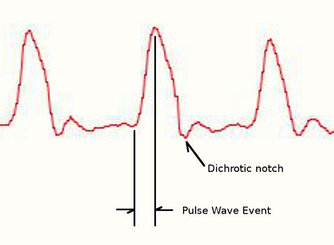
The Pulse Sensor that we make is essentially a photoplethysmograph (PPG), which is a well known medical device used for non-invasive heart rate monitoring. Sometimes, PPGs measure blood-oxygen levels (SpO2), sometimes they don't. The heart pulse signal that comes out of a PPG is an analog fluctuation in voltage, and it has a predictable wave shape as shown in figure 1. The depiction of the pulse wave is called a photoplethysmogram, or PPG. Our latest hardware version, Pulse Sensor Amped, amplifies the raw signal of the previous Pulse Sensor, and normalizes the pulse wave around V/2 (midpoint in voltage). Pulse Sensor Amped responds to relative changes in light intensity. If the amount of light incident on the sensor remains constant, the signal value will remain at (or close to) 512 (midpoint of Arduino 10 bit ADC range). More light and the signal goes up. Less light, the opposite. The amount of light from the green LED that is reflected back to the sensor changes during each pulse.
Our goal is to find successive moments of instantaneous heart beat and measure the time between, called the inter-beat interval (IBI). By following the predictable shape and pattern of the PPG wave, we are able to do just that.
Now, we're not heart researchers, but we play them on this blog. We're basing this page on Other People's Research that seem reasonable to us (references below). When the heart pumps blood through the body, with every beat there is a pulse wave (kind of like a shock wave) that travels along all arteries to the very extremities of capillary tissue like fingertips and earlobes where the Pulse Sensor is most likely attached. We are measuring the change in tissue density due to the pulse wave, actual blood circulates in the body much slower than the pulse wave travels. Let's follow events as they progress from point 'T' on the PPG below. A rapid upward rise in signal value occurs as the pulse wave passes under the sensor, then the signal falls back down toward the normal point. Sometimes, the dicroic notch (downward spike) is more pronounced than others, but generally the signal settles down to background noise before the next pulse wave washes through. Since the wave is repeating and predictable, we could choose almost any recognizable feature as a reference point, say the peak, and measure the heart rate by doing math on the time between each peak. This, however, can run into false readings from the dicroic notch, if present, and may be susceptible to inaccuracy from baseline noise as well.There are other good reasons not to base the beat-finding algorithm on arbitrary wave phenomena. Ideally, we want to find the instantaneous moment of the heart beat. This is important for accurate BPM calculation, Heart Rate Variability (HRV) studies, and Pulse Transit Time (PTT) measurement. And it is a worthy challenge! People Smarter Than Us (note1) argue that the instantaneous moment of heart beat happens at some point during that fast upward rise in the PPG waveform.

Some heart researchers say it's when the signal gets to 25% of the amplitude, some say when it's 50% of the amplitude, and some say it's the point when the slope is steepest during the upward rise event. This version 1.1 of Pulse Sensor code is designed to measure the IBI by timing between moments when the signal crosses 50% of the wave amplitude during that fast upward rise. The BPM is derived every beat from an average of the previous 10 IBI times. So, when the Arduino is powered up and running with Pulse Sensor Amped plugged into analog pin 0, it constantly (every 2 mS) reads the sensor value and looks for the heart beat.
note1: Seems the folks who argue most about where the instantaneous moment of heart beat is are trying to measure Pulse Transit Time. PTT measures how long it takes for the pulse to travel from the point R on an Electro Cardiogram (ECG) to an extremity (fingertip/toe). PPG is often used in PTT studies to time pulse arrival at the extremity. Somnologists sometimes use PTT. Check the references for dorking out on acronyms!
References
http://thorax.bmj.com/content/54/5/452.full
http://www.ncbi.nlm.nih.gov/pmc/articles/PMC1763783/pdf/v054p00452.pdf
http://lcp.mit.edu/pdf/DeshmaneThesis09.pdf
http://www.somnomedics.eu/fileadmin/SOMNOmedics/Dokumente/article_Gesche_et_al_-_Continuous_BP_Measurement_by_using_the_PTT_Comparison_to_cuff_based_method.pdf
http://www.ncbi.nlm.nih.gov/pubmed/8586120
http://erj.ersjournals.com/content/8/10/1669.long
http://www.hoc.kit.edu/downloads/PTT_for_stress-measurement_final_2.pdf
http://journal.publications.chestnet.org/article.aspx?articleid=1083218
http://iopscience.iop.org/1742-6596/307/1/012060/pdf/1742-6596_307_1_012060.pdf
http://erj.ersjournals.com/content/8/10/1669.long
http://iopscience.iop.org/1742-6596/307/1/012060/pdf/1742-6596_307_1_012060.pdf
http://daily.ctia.org/files/WIRELESS2011/showsite/doc/RC_-_Noninvasive_Cuffness.pdf
http://www.wpi.edu/Pubs/ETD/Available/etd-073106-130906/unrestricted/wjohnston.pdf