
PulseSensor on CYD (ESP32-2432S028)
PulseSensor CyberDeck on the CYD (ESP32-2432S028)
Try it now: Plug your CyberDeck into USB, click Install below, then wire up your PulseSensor. Live heartbeat on a 320×240 TFT in under two minutes — with sound, blinking light, and on-screen volume control. No app to install, no WiFi, no IDE. Just Chrome, Edge, or Brave.
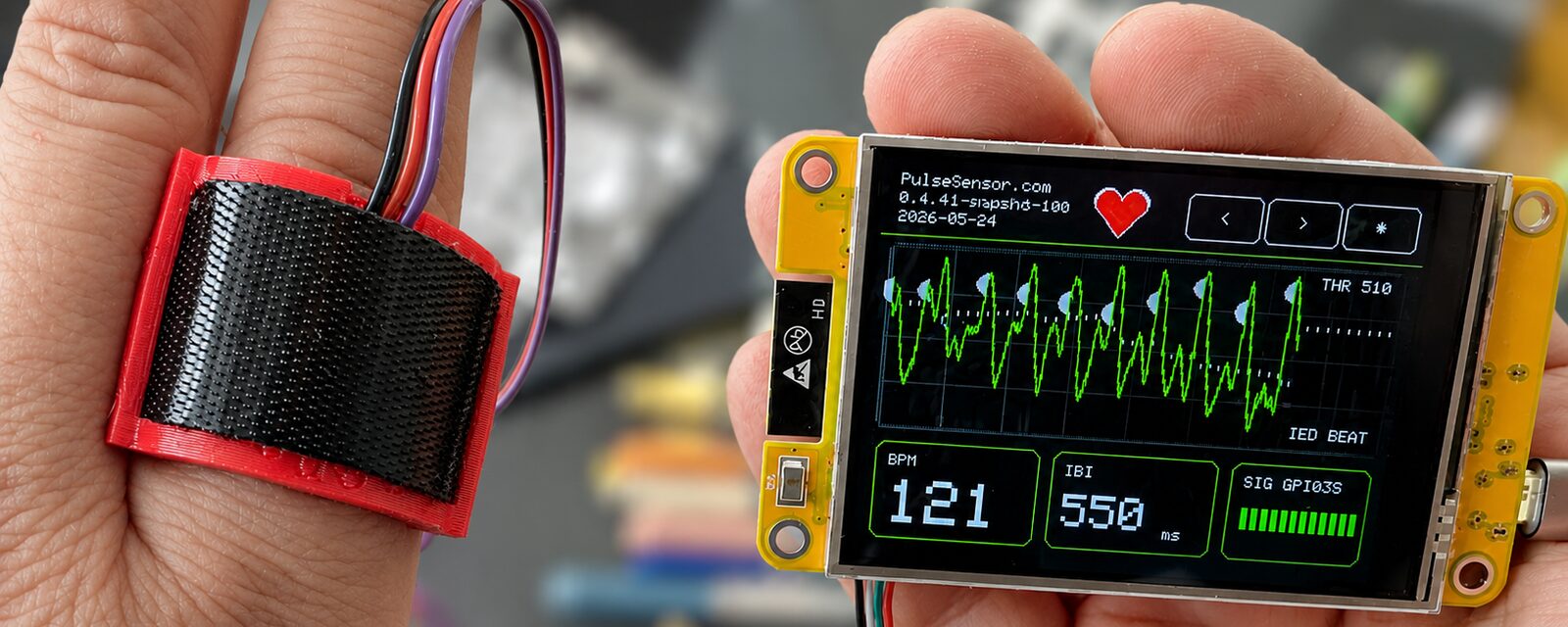
What's a CYD?
"CYD" is the maker community's nickname for the ESP32-2432S028 — short for "Cheap Yellow Display," after the bright yellow PCB the early boards shipped on. For pocket change you get an ESP32 microcontroller, a 2.8″ 320×240 color touchscreen, an SD card slot, and a speaker pin in one tiny package. That bundle is why it exploded in the maker community as the go-to board for portable dashboards, retro mini-games, smart-home displays, and — with this firmware — live heart-rate biofeedback.
Credit where it's due: YouTuber Brian Lough is who put the CYD on the map. His "Cheap Yellow Display" video series, Discord, and stream of starter projects turned a random AliExpress board into a thriving maker community — and gave thousands of people their first taste of building a portable touchscreen device.
We call our build of it the PulseSensor CyberDeck — a CYD running open-source PulseSensor firmware, ready to flash from this page.
⚡ Flash Your CyberDeck
Installer firmware: 1.3.0-launch - 2026-05-26. After flashing, the dashboard should show the same version and date under PulseSensor.com.
First time? After you click Install, your browser will ask which serial port to use. Pick the one labeled with your board's USB-serial chip (often CP210x or CH340).
Wire Your PulseSensor
The PulseSensor uses three color-coded wires. Use this two-step guide before you connect the sensor.
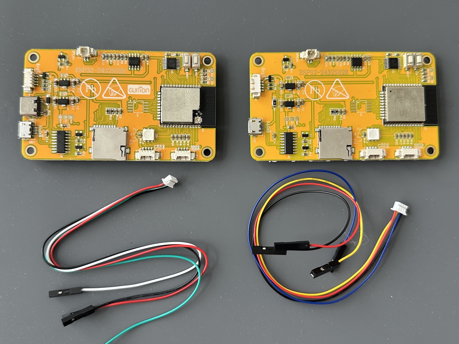
Identify your board and harness
Look for the ESP32-2432S028 number in the listing or printed on the board.
- Single micro-USB style works.
- Micro-USB plus USB-C style works.
- Make sure it includes a JST-SH 1.0 mm to Dupont jumper harness.
- Harness colors vary by seller; the board labels matter most.
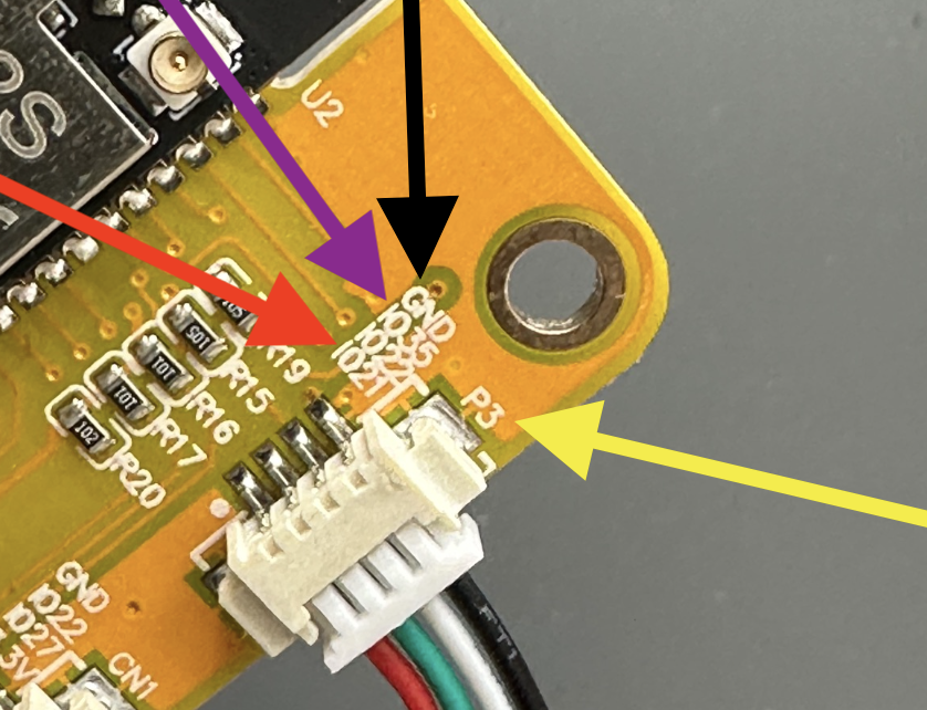
Wire P3 by label
Plug the white harness into P3, then match the PulseSensor wires to the board labels.
-
Red
IO21on P3 -
Black
GNDon P3 -
Purple
IO35on P3
Important: Use P3 IO21 as PulseSensor power, not 5V. The firmware reads the PulseSensor signal from P3 IO35.
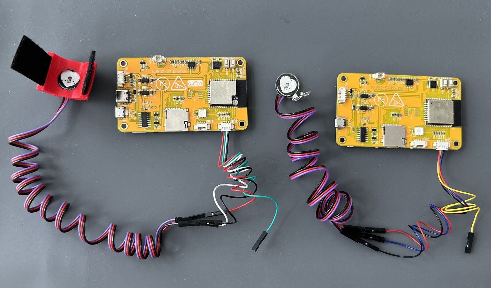
What You'll See
After you flash and wire up, press your finger lightly on the sensor. You'll see two states:
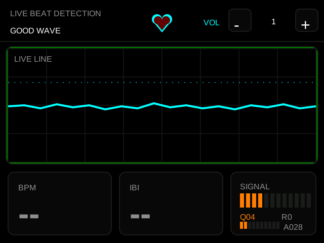
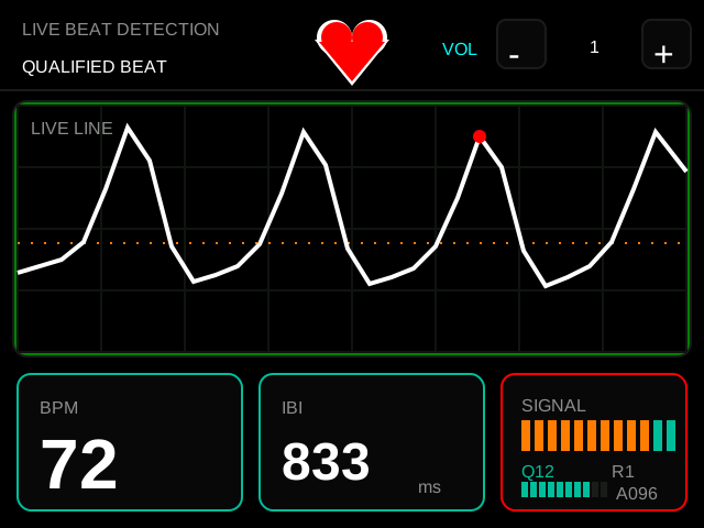
The dashboard tells you what state it's in at a glance:
-
Yellow → Green. The waveform starts yellow while the firmware searches for clean beats, then turns green once the quality meter locks at
10/12. -
Header flips.
SIGNAL SEARCHbecomesQUALIFIED BEATthe moment lock happens. - Numbers settle. BPM, IBI (milliseconds between beats), and the animated heart all sync to your rhythm. The pulse amplitude meter rises with stronger signals.
Features
Four feedback channels turn the CyberDeck into a complete biofeedback teaching tool.
- Smooth waveform. Clear peaks matching your heartbeat — yellow first, then green once locked.
- BPM stabilizes. Settles to 60–100 within 5–10 seconds.
- Heart pulses. The header heart and rear red LED flash on every qualified beat.
- Sound + light. Short heartbeat tone on each qualified beat.
PulseSensor Playground Tie-Ins
Every reading on the screen comes directly from the PulseSensor Playground library, so what you see on the ESP32-2432S028 display is what you'd see in your own Arduino sketches.
| What you see on screen | Playground call behind it |
|---|---|
| Live waveform | getLatestSample() |
| Heart pulse / LED blink / tone | sawStartOfBeat() |
| "Inside beat" indicator | isInsideBeat() |
| BPM number | getBeatsPerMinute() |
| IBI number | getInterBeatIntervalMs() |
| Amplitude meter | getPulseAmplitude() |
| Dotted threshold line | setThreshold(550) |
Quick Troubleshooting
| Problem | Fix |
|---|---|
| Install button does nothing | Use Chrome, Edge, or Brave on a desktop or laptop. Mobile browsers don't support WebSerial yet. |
| No serial port appears in the picker | Try a different USB cable — many micro-USB cables are charge-only. Plug directly into your computer, not a hub. |
| Flashes but screen stays blank | The CYD backlight is on GPIO 21. If it's truly dark, you may have a different board variant. Open an issue with your board photo. |
| Flat waveform | Confirm the purple wire is on P3 IO35 and the red wire is on P3 IO21. Do not use 5V. |
| Erratic readings | Use gentle, steady finger pressure. Insulate the back of the sensor. Try the Stabilizer Ring for the cleanest signal. |
| BPM stays at 0 | Give it 5–10 seconds. The detector needs a few clean beats before it reports BPM. |
PulseSensor CyberDeck Matrix
A cyberdeck is whatever board you build it on. These are the PulseSensor CyberDecks so far — same heartbeat engine, different screens:
| CyberDeck | PulseSensor CyberDeck (CYD) | PulseSensor RLCD — LiveCyberDeck |
|---|---|---|
| Board | ESP32-2432S028 "Cheap Yellow Display" | Waveshare ESP32-S3-RLCD-4.2 |
| Screen | 320 × 240 color touchscreen (backlit) | 400 × 300 reflective (no backlight) |
| Best for | Indoors, color & touch | Daylight, outdoors, eye comfort |
| Extras | Touch, speaker beep, rear LED | Battery %, temperature & humidity, sparklines |
| Power pin | IO21 |
3V3 |
| Ground pin | GND |
GND |
| Signal pin | IO35 |
GP1 / GPIO1
|
| Flash | Browser (ESP Web Tools) | Browser (ESP Web Tools) |
Advanced Notes
Hardware details and pinout
The firmware targets the ESP32-2432S028 board family, commonly sold under the "Cheap Yellow Display" nickname, with an ILI9341 320×240 TFT and XPT2046 resistive touch.
PULSE_PIN       = 35
BACKLIGHT       = 21
LED_RED_PIN     = 4
LED_GREEN_PIN   = 16
LED_BLUE_PIN    = 17
SPEAKER_PIN     = 26
TOUCH_IRQ       = 36
TOUCH_MISO      = 39
TOUCH_MOSI      = 32
TOUCH_SCLK      = 25
TOUCH_CS        = 33
Why GPIO 35? The PulseSensor signal pin was discovered with a small analog pin scanner on a connected CYD. On this revision the signal was visible on IO35, not the originally documented GPIO 36.
ESP32 analog quirk. PulseSensorPlayground's detector expects 10-bit analog samples (0..1023), but ESP32 defaults to 12-bit (0..4095). The firmware calls analogReadResolution(10) at startup to keep the library's beat-detection math in the range it expects.
Build from source in Arduino IDE
- Download
PulseSensor_CYD.inofrom the repo. - Make a folder named
PulseSensor_CYD. Put the.inoinside it. - Open it in Arduino IDE 2.x.
- Install the ESP32 board package (Boards Manager).
- Install three libraries:
TFT_eSPI,PulseSensor Playground,XPT2046_Touchscreen. - Configure
TFT_eSPIfor the ESP32-2432S028 display (the repo'sflash-cyd.shscript shows the exact compile flags — preferred over editing the globalUser_Setup.h). - Select your ESP32 board and upload at
115200baud.
Get the Source / Get a Sensor
Prefer to see it in a browser without a screen? Try PulseSensor + WebSerial — same sensor, dashboard runs in Chrome.
📂 The Source Code
The firmware is intentionally one Arduino .ino file so you can open, read, and modify it in the Arduino IDE.
github.com/WorldFamousElectronics/PulseSensor_CYD
MIT licensed. PRs welcome.
🛒 Need a PulseSensor?
The PulseSensor Kit ships with a TPU Stabilizer Ring, color-coded cable, ear clip, finger strap, and vinyl insulation dots.
This software is an educational biofeedback demo and is not intended for medical use.
Made by World Famous Electronics. Source on GitHub. MIT licensed. Heartbeats in your project, lickety-split. ♥